 Australian owned · Locally engineered
 1300585787
 sales@protector.com.au


Direct the inflow
The inlet weir directs water into the vortex flow path.
Primary treatment
Capture more at the first stage.
Primary stormwater treatment for litter, debris and sediment, with a dedicated pollutant storage chamber.
Product selection · Project drawings · Technical support
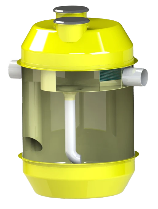
The system, explained
EcoProtector uses an inlet weir and vortex flow path to separate gross pollutants and sediment. Captured material is stored for removal during maintenance, while the high-flow arrangement allows water to pass through the system.
Explore our engineering supportHow it works
The inlet weir directs water into the vortex flow path.
Gross pollutants and sediment move into the storage chamber.
Dedicated access allows inspection and pump-out of retained material.
Where it fits
For designers & specifiers
Start with the project requirements.
We’ll help you confirm the right configuration.
Confirm gross pollutant and sediment treatment objectives.
State treatment flow and peak bypass flow.
Select pollutant storage capacity and a maintenance interval suited to the catchment.
Provide pipe sizes, orientation, invert levels and downstream constraints.
Confirm cover loading, groundwater, excavation and backfill requirements.
Provide pump-out access and request model-specific drawings and maintenance instructions.
Complete the bracketed project details and confirm the selected model with Protector.
Final dimensions, capacities and installation details are established in the approved project drawings and current manufacturer documentation.
Request a project-specific specificationTechnical data
Model selection reference. Confirm current dimensions, capacities and connection details against the approved project drawing.
| Model ID | Treatment flow (L/s) | Internal Diameter (MM) | Depth Below Invert (MM) | Max Pipe Size (MM) | Sump Capacity (M3) |
|---|---|---|---|---|---|
| ECP.1200 | 32 | 165 | 1200 | 2200 | 100 - 375 |
| ECP.1500 | 105 | 480 | 1500 | 2400 | 100 - 375 |
| ECP.1850 | 135 | 1020 | 1850 | 2550 | 225 - 600 |
| ECP.2200 | 288 | 2900 | 2200 | 2550 | 375 - 900 |
| ECP.2500 | 448 | 9500 | 2500 | 3500 | 600 - 1350 |
| ECP.3000 | 894 | 13780 | 2500 | 2500 | 4500 |
| ECP.3500 | 1905 | 22118 | 3500 | 5000 | 600 - 1800 |
Downloads & technical support
Access product documents or ask our team for the current package for your project.
Access the existing product document request page.
Open document page Project-specific packageRequest the current model drawing, sizing guidance and specification for your site.
Request technical package Project supportCoordinate the treatment train, hydraulic requirements and product layout.
Explore engineering In practiceSee applications and installations from the project archive.
Explore projects Project filmWatch the project video from the original resource collection.
Watch on YouTubeLet’s work together
Tell us about your site, your objectives and where you need support.


