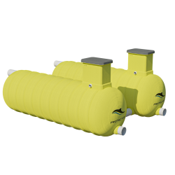
HydroProtector
HydroProtector Overview
- INDEPENDENTLY CERTIFIED TO CLASS 1,EN 858.1 STANDARD
- FAIL-SAFE AUTOMATIC CLOSURE DEVICE
- INTEGRATES INLET FLAME TRAP
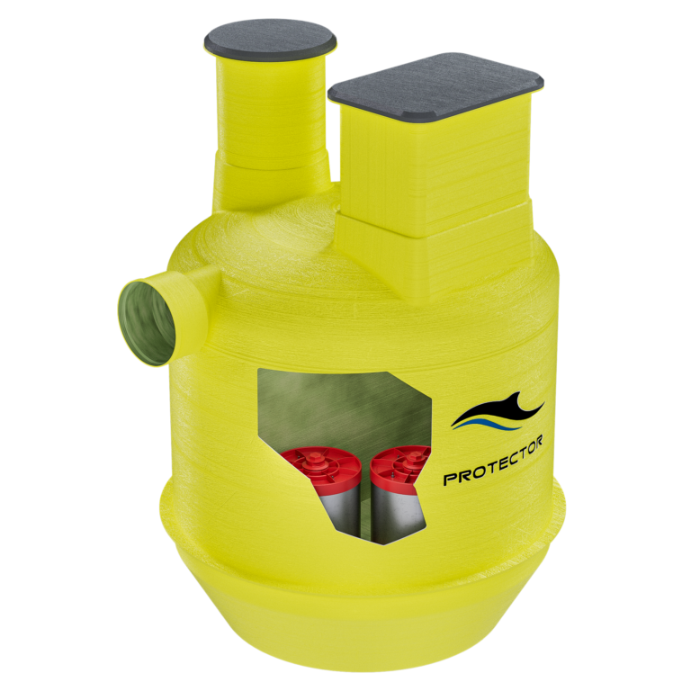
- STRONG FRP DUAL CHAMBER CONSTRUCTION WITH WEIGHT SAVING ADVANTAGE
- OIL MONITORING SENSOR WITH AUDIBLE AND VISUAL ALARM
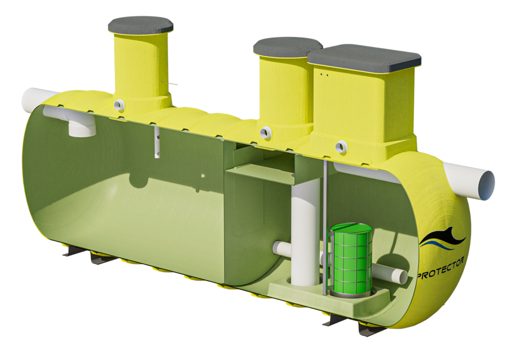
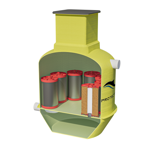
- SECONDARY CHAMBER FITTED WITH A COALESCER FILTER
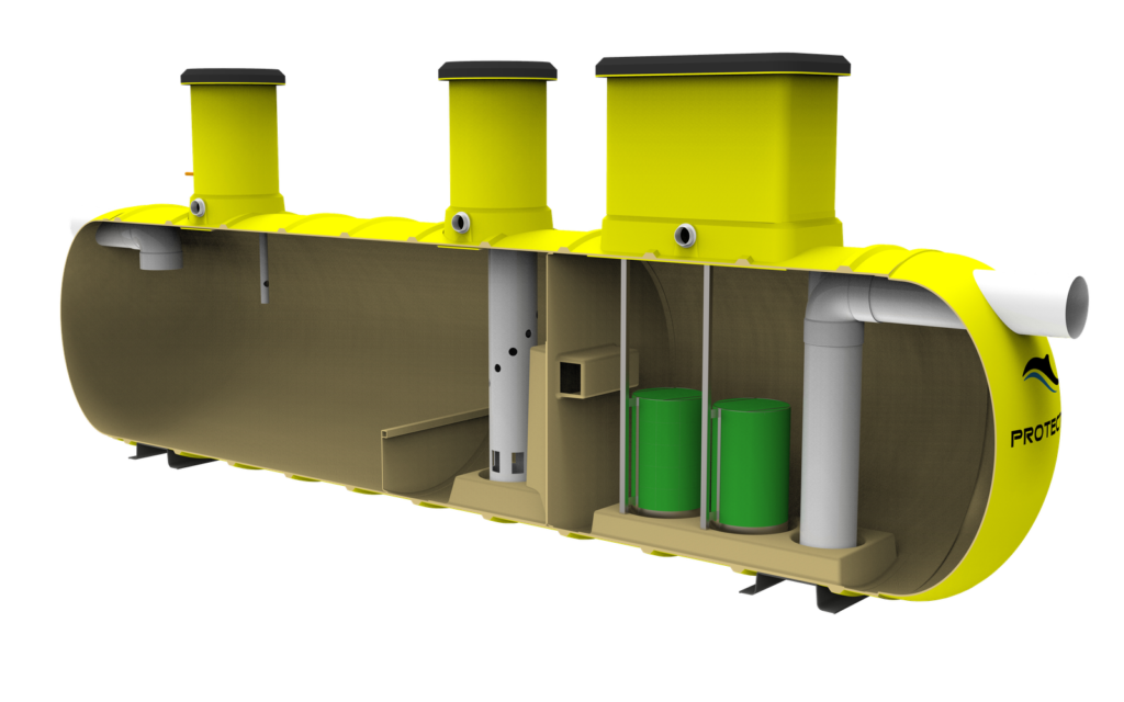
HydroProtector
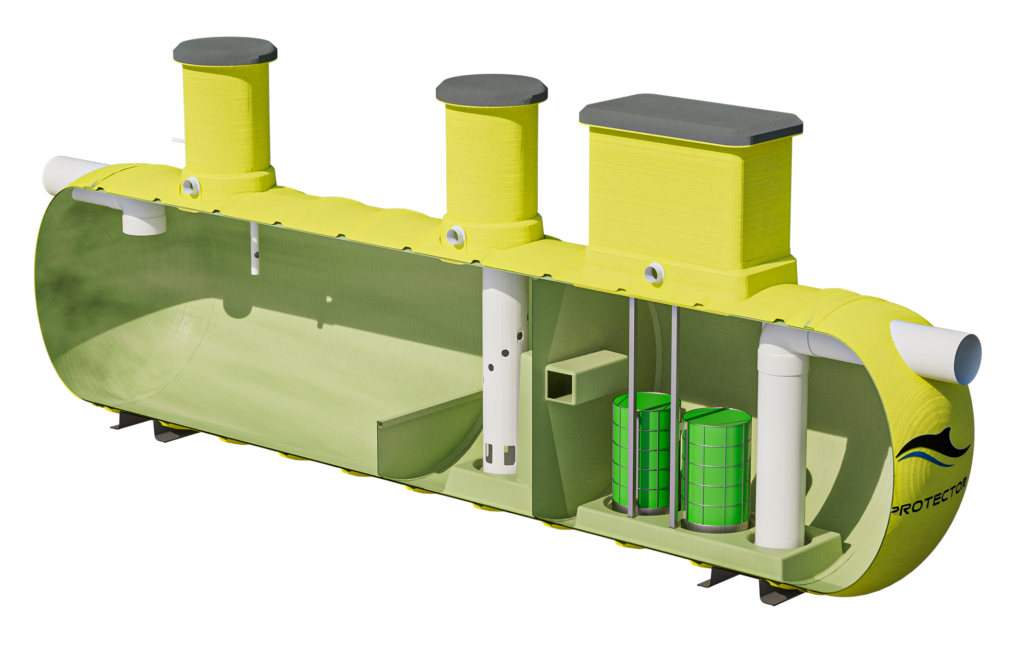
HydroProtector systems are autonomous and gravity operated, therefore they will function without electricity. They are engineered to meet the European Standard EN858:1: 2002 and have been independently tested for discharge water quality of less than 5mg/l and also achieve percentage removal rates of nitrogen and phosphorus.
All HydroProtector models are independently certified for hydrocarbon spill capture volumes. Hydraulic out to ensure capacity and flowrate accuracy.
The HydroProtector is a full-retention separator that does not allow any liquids to be bypassed, therefore all flows into the unit are treated. The HydroProtector has an incorporated flame trap, an automatic closure device, and a two-chamber design that protects the coalescer that is fitted at the outlet from inundation in the event of a spill. HydroProtector units are manufactured to treat stormwater flow rates from 2 l/s up to 350 l/s with a maximum pipe size of 750mm.
Why install a HydroProtector
Installing a Hydroprotector is a practical decision for several reasons. First and foremost, it plays a crucial role in high risk environments. Hydroprotector s effectively contain and mitigate spills, preventing. hazardous substances like oil or chemicals from contaminating soil and water sources. This helps businesses meet regulatory compliance and minimize their environmental impact, contributing to a sustainable and responsible approach to operations.
Secondly, Hydroprotectors are cost-effective solutions. By swiftly containing spills, they reduce the potential for costly cleanup efforts, legal liabilities, and damage to equipment. Their ease of installation and low maintenance requirements further enhance their cost-efficiency.
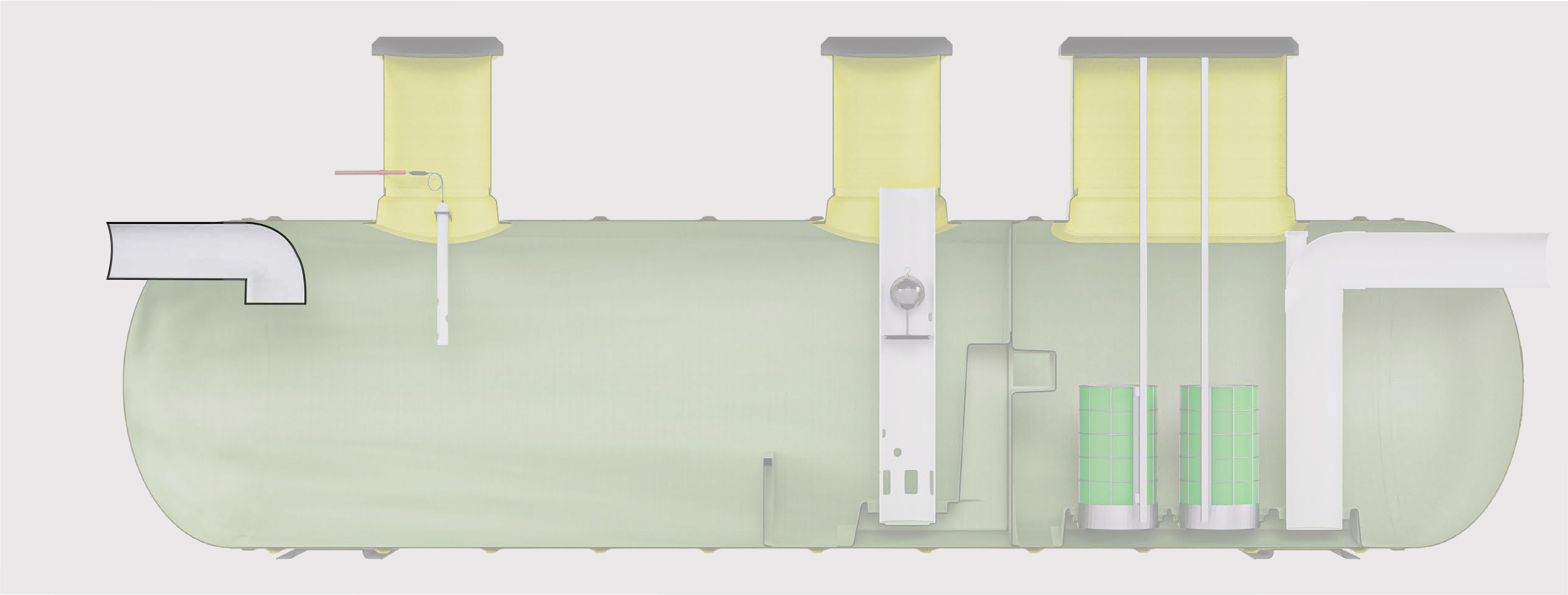
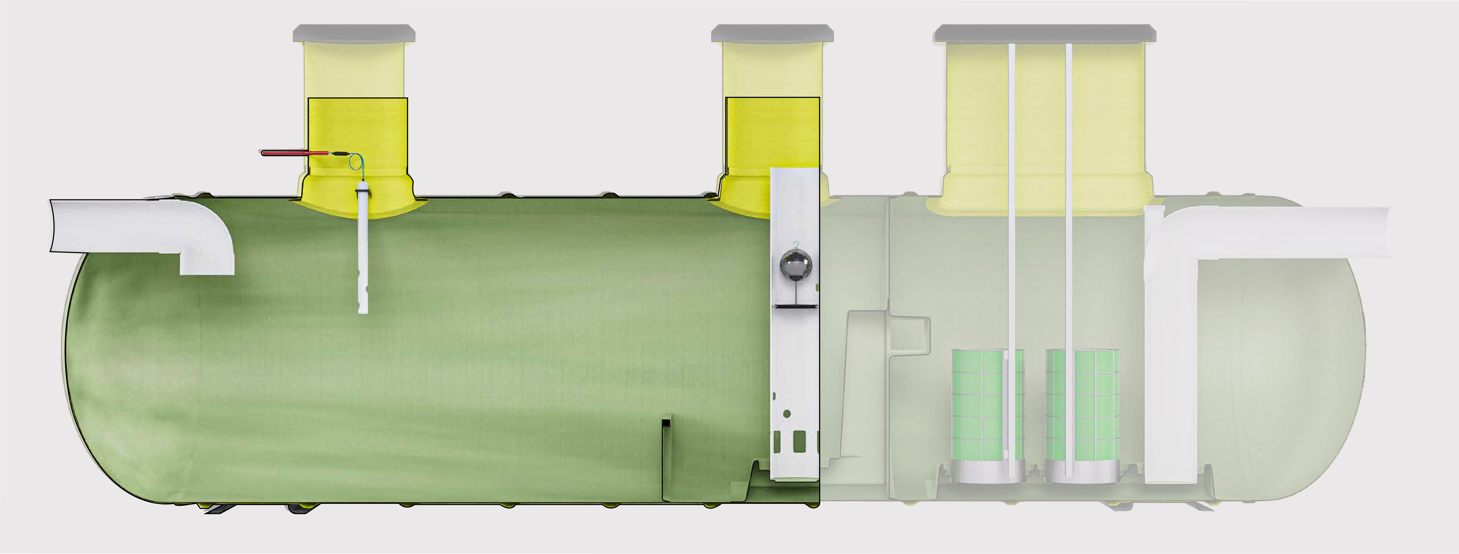
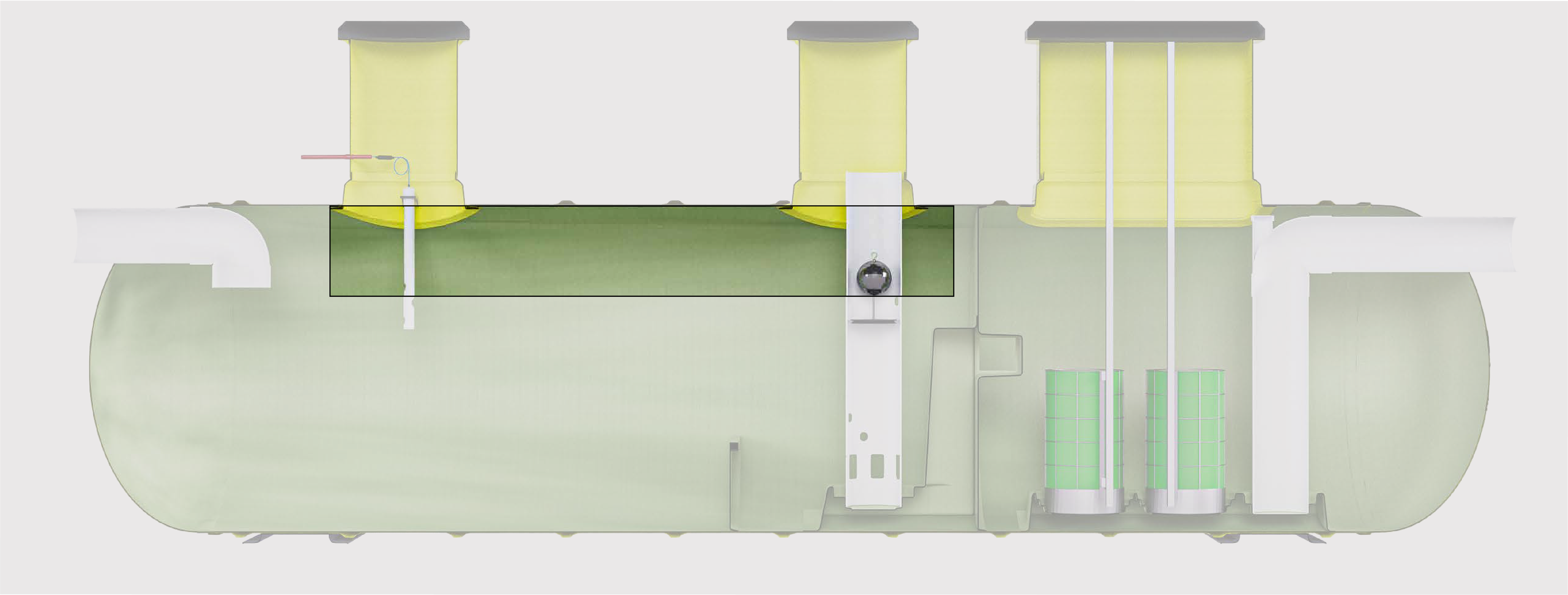
Step One
FLAME TRAP INLET
The inlet pipe features a flame trap which works by eliminating air from the liquids entering the primary chamber.
Step Two
PRIMARY CHAMBER
The primary chamber of the Stormprotector is designed to slow down and separate pollutants from stormwater runoff, allowing dense particles to settle at the bottom of the chamber and the lighter fluids and deris to rise to the surface while the cleaner water flows into the secondary chamber for further treatment.
Step Three
OIL CAPTURE
Captured hydrocarbons rise to the surface of the storage chamber and are retained behind a weir which stops them from flowing into the secondary chamber without resuspension during high flow events.
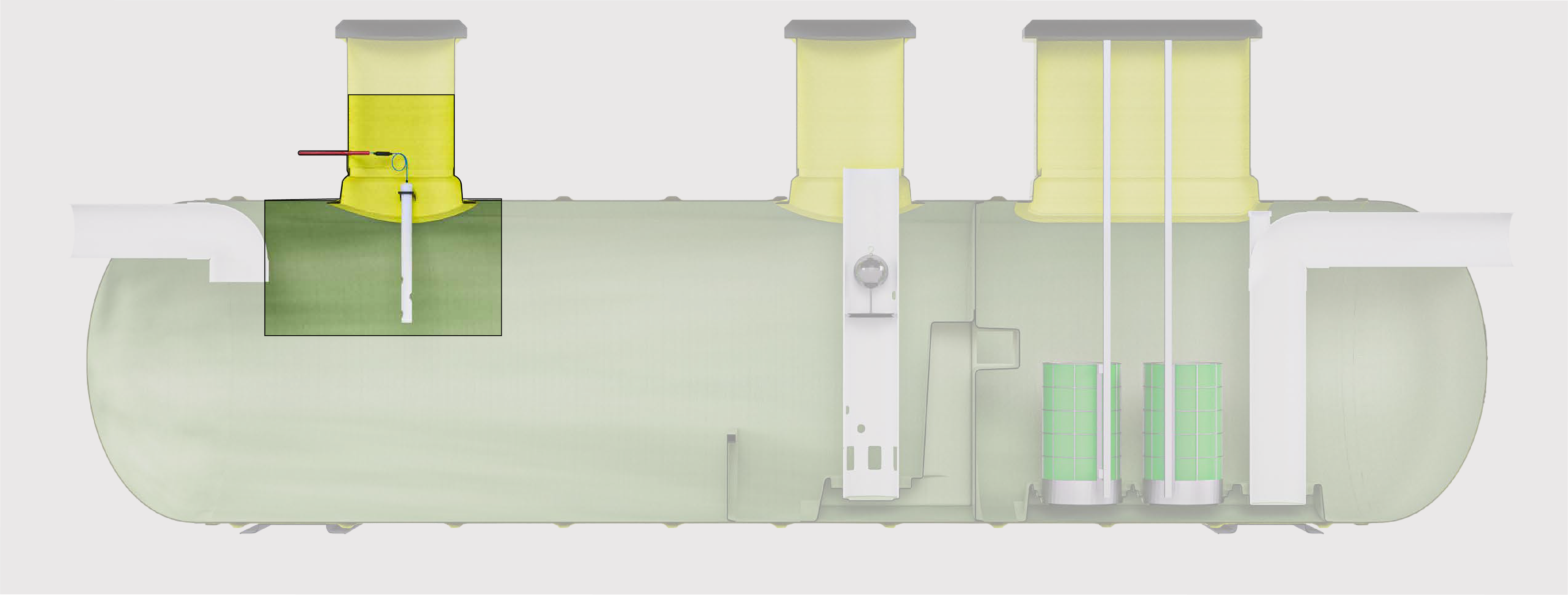
Step Four
OIL PROBE CONTROL PANEL AND VAPOUR Y-SEAL
The Stormprotector is easily maintained due to its trash, oiland sludge pumpout access, providing easy and efficient access for regular maintenance and cleaning.
Step Five
SLUGE WEIR (OPTIONAL)
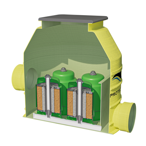
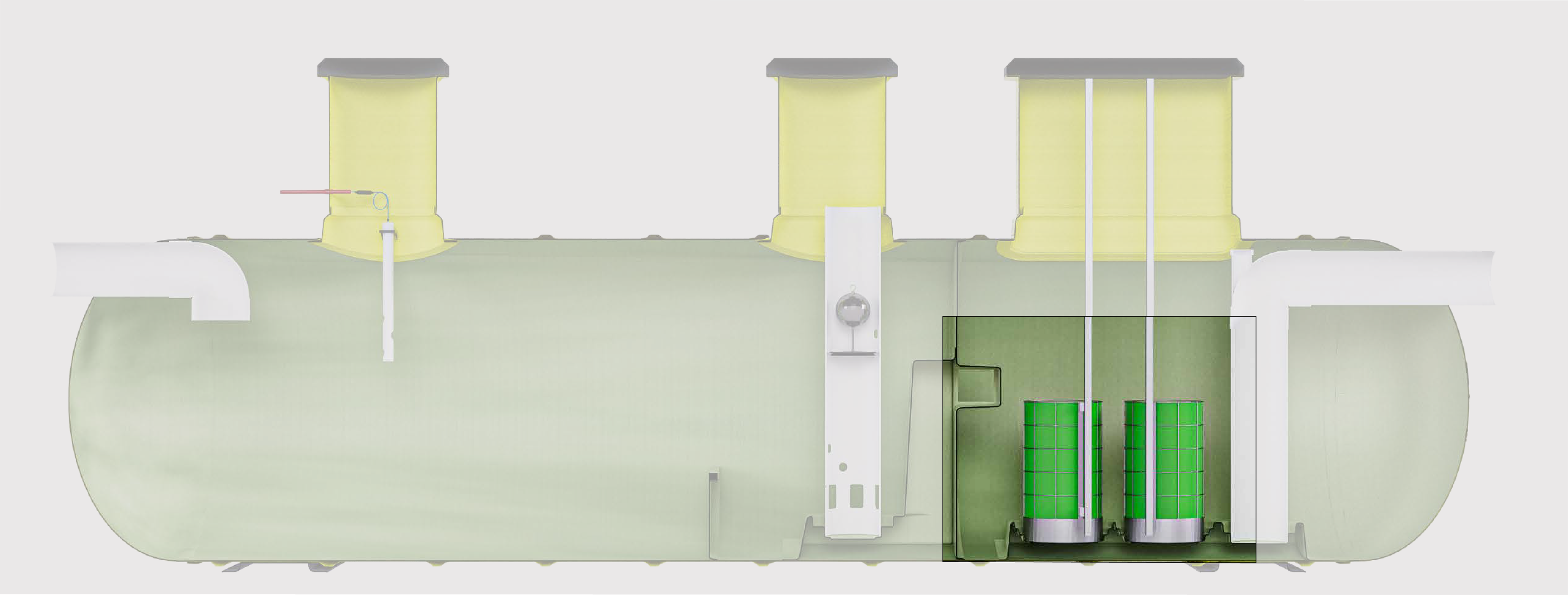
The secondary chamber is fitted with a finely perforated coalescing unit which removes the remaining globules of light liquid to a certified 5mg/l. The coalescing unit is installed on guiderails for ease of installation and maintenance.
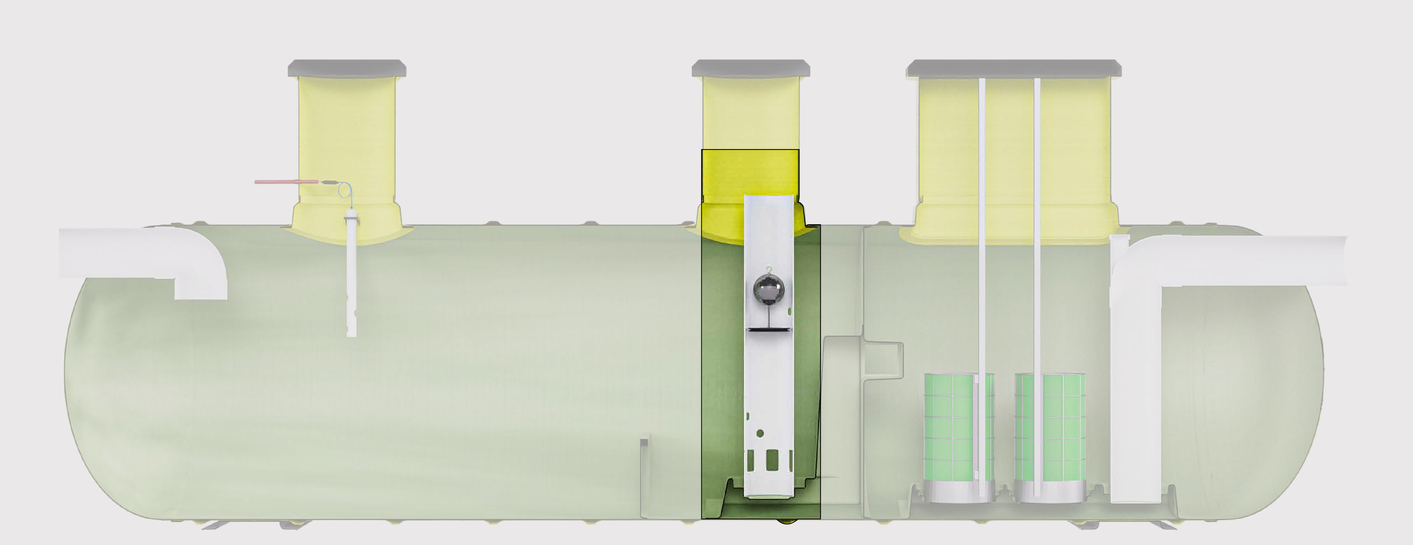
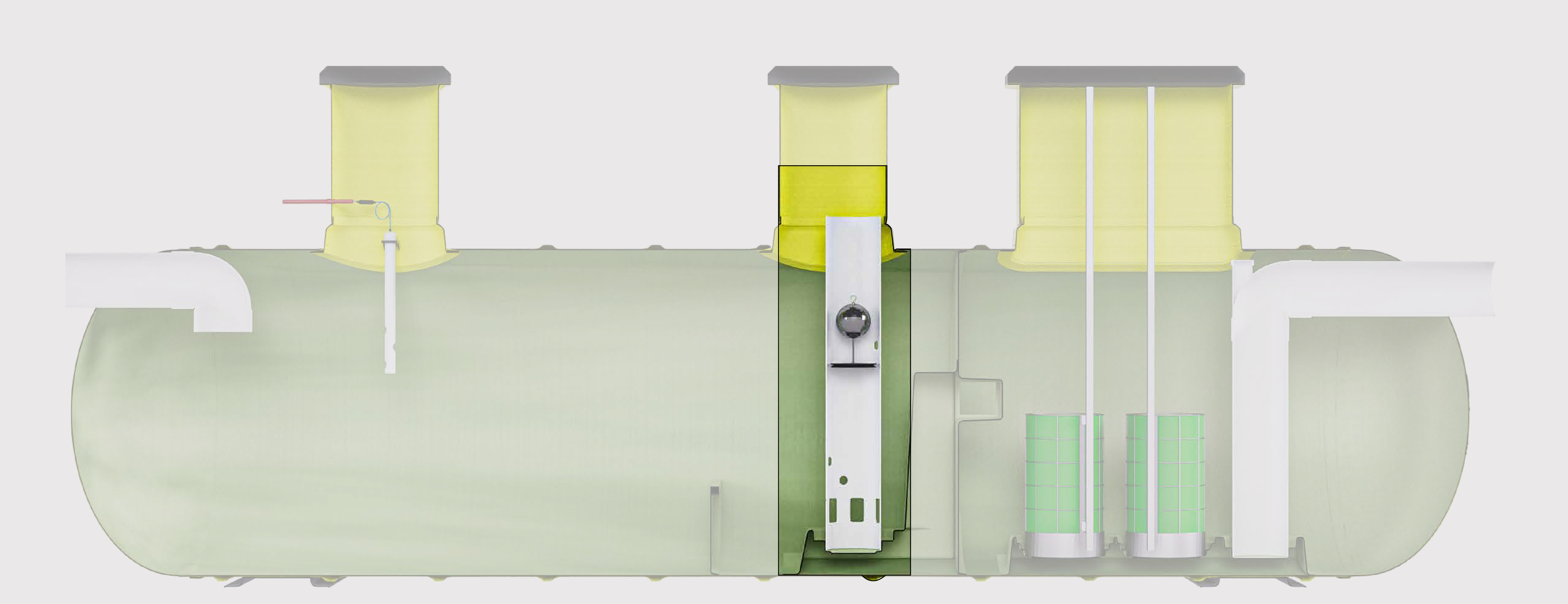
Step Six
AUTOMATIC CLOSURE DEVICE
The Stormprotector has a max flow bypass that allows water to discharge freely over the weir during large stormwater inflows to prevent flow restriction.
Step Seven
COALESCER FILTER UNIT
The oil probe and control panel are crucial components in monitoring and maintaining oil spills. The probe detects any oil leaks and sends signals to the control panel, which alerts the maintenance team.
Step Eight
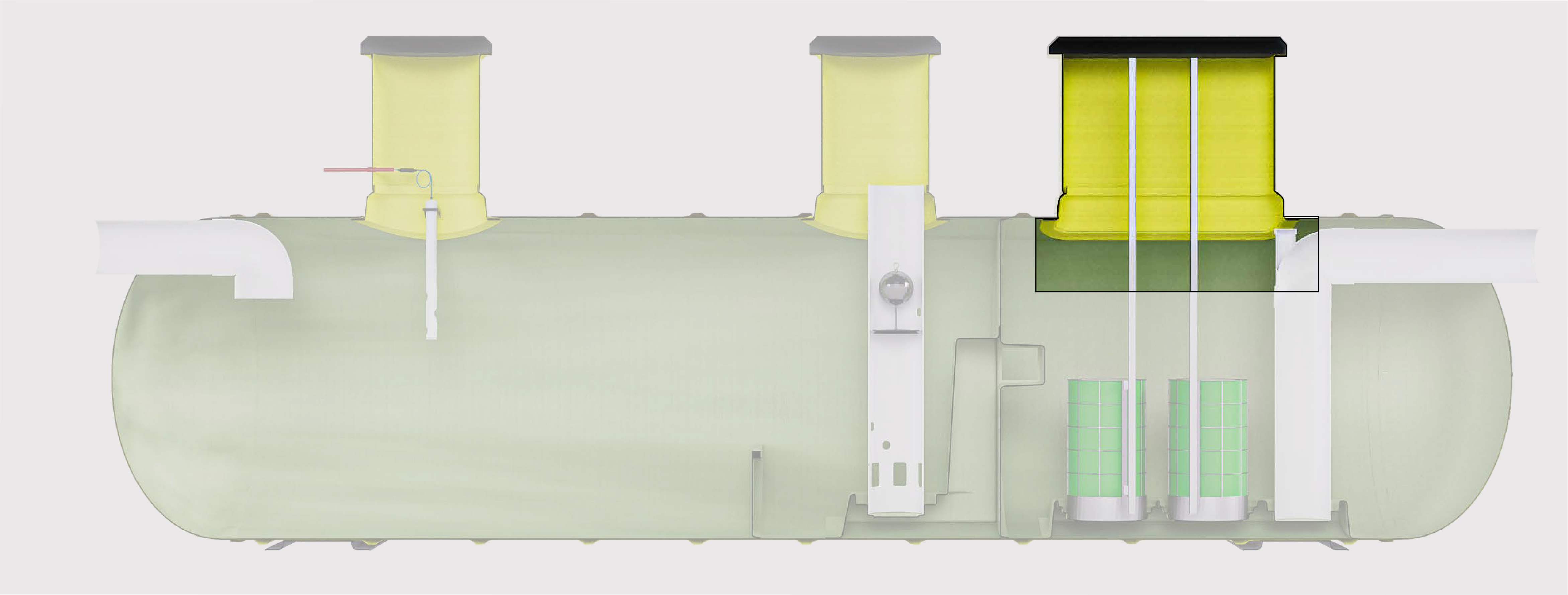
INNOVATIVE RISER DESIGN
The oil probe and control panel are crucial components in monitoring and maintaining oil spills. The probe detects any oil leaks and sends signals to the control panel, which alerts the maintenance team.
Product Application
- SERVICE STATIONS
- ULK FUEL STORAGE FACILITIES
- ELECTRICAL SUBSTATIONS
- TRANSPORT REFUELING AREAS
- WINDFARMS
- AIRCRAFT APRONS
- ASPHALT PLANTS
- MINING WASH DOWN AREAS
Product Specification
| Model ID | Treatment Flow Rate (L/s) ) |
Spill Capacity (L) |
Total capacity (L) | Unit Length (L) | UNIT DEPTH (MM | STANDARD PIPEWORK DIA (MM) ) | DRAWING |
|---|---|---|---|---|---|---|---|
| HYD.2.DC.R2-1 | 2 | 343 | 791 | 1099 | 1050 | 100 |
|
| HYD.4.DC.R2-1 | 4 | 617 | 1551 | 2100 | 1050 | 150 |
|
| HYD.8.DC.R2-1 | 8 | 1344 | 2984 | 3000 | 1200 | 150 |
|
| HYD.13.DC.R4-1 | 13 | 2436 | 4896 | 2370 | 1500 | 225 |
|
| HYD.15.DC.R4-1 | 15 | 2790 | 5616 | 3750 | 1500 | 225 |
|
| HYD.20.DC.R4-1 | 20 | 4033 | 7495 | 3350 | 1850 | 300 |
|
| HYD.30.DC.R5-1 | 30 | 6006 | 11,228 | 5450 | 1850 | 300 |
|
| HYD.40.DC.R6-1 | 40 | 10,008 | 14,950 | 7460 | 1850 | 300 |
|
| HYD.50.DC.R5-2 | 50 | 10,031 | 18,678 | 8000 | 1850 | 300 |
|
| HYD.60.DC.R5-2 | 60 | 11,923 | 22,405 | 9550 | 1850 | 300 |
|
| HYD.70.DC.R5-2 | 70 | 14,951 | 26,224 | 7900 | 2200 | 300 |
|
| HYD.80.DC.R6-2 | 80 | 17,022 | 29,888 | 8850 | 2200 | 300 |
|
| HYD.100.DC.R5-3 | 100 | 21,262 | 37,392 | 11,000 | 2200 | 300 |
|
| HYD.110.DC.R5-3 | 110 | 23,848 | 41,469 | 9950 | 2500 | 450 |
|
| HYD.120.DC.R6-3 | 120 | 25,939 | 45,131 | 10,800 | 2500 | 450 |
|
| HYD.150.DC.R5-4 | 150 | 32,209 | 56,116 | 13,350 | 2500 | 450 |
|
| HYD.180.DC.R6-4 | 180 | 40,983 | 67,949 | 11,000 | 3000 | 450 |
|
| HYD.200.DC.R6-4 | 200 | 47,297 | 76,029 | 9000 | 3500 | 450 |
|
| HYD.250.DC.R7-4 | 250 | 58,239 | 93,825 | 11,000 | 3500 | 300 |
|
| HYD.300.DC.R7-5 | 300 | 69,728 | 112,511 | 13,100 | 3500 | 750 |
|
| HYD.350.DC.R7-5 | 350 | 80,943 | 130,751 | 15,150 | 3500 | 750 |
|
Enquire with us
Today!
Call 1300 585 787
Southern Highlands 1 Government Road, Braemar, NSW, 2575
Email: sales@protector.com.au
Phone: 1300 585 787
Give us a call or drop by anytime, we endeavour to answer all enquiries within 24 hours on business days.
- TRAP-IT- GROSS POLLUTANT
- ECOPROTECTOR - HIGH CAPACITY GROSS POLLUTANT TRAP
- TORNADO - HIGH FLOW CONTINUOUS DEFLECTION SEPERATION GPT
- HYDROPROTECTOR - CLASS 1 HYDROCARBON SPILL CONTAINMENT AND OIL SEPERATION
- STORMPROTECTOR - MEDIUM RISK STORMWATER TREATMENT
- BIOPROTECTOR - PHYSICAL AND BIOLOGICAL FILTRATION
Call Us
1 300 585 787
Head Office
Southern Highlands , 1 Government Rd, Braemar NSW 2575
sales@protector.com.au

© 2024 Protector. All rights reserved.
Please fill out the following details so we can send the document to you.
Please fill out the following details so we can send the document to you.
Please fill out the following details so we can send the document to you.
Please fill out the following details so we can send the document to you.
Please fill out the following details so we can send the document to you.
Please fill out the following details so we can send the document to you.
Please fill out the following details so we can send the document to you.
Please fill out the following details so we can send the document to you.
Please fill out the following details so we can send the document to you.
Please fill out the following details so we can send the document to you.
Please fill out the following details so we can send the document to you.
Please fill out the following details so we can send the document to you.
Please fill out the following details so we can send the document to you.
Please fill out the following details so we can send the document to you.
Please fill out the following details so we can send the document to you.
Please fill out the following details so we can send the document to you.
Please fill out the following details so we can send the document to you.
Please fill out the following details so we can send the document to you.
Please fill out the following details so we can send the document to you.
Please fill out the following details so we can send the document to you.
Please fill out the following details so we can send the document to you.
Please fill out the following details so we can send the document to you.
Please fill out the following details so we can send the document to you.
Please fill out the following details so we can send the document to you.
Please fill out the following details so we can send the document to you.
Please fill out the following details so we can send the document to you.
Please fill out the following details so we can send the document to you.
Please fill out the following details so we can send the document to you.
Please fill out the following details so we can send the document to you.
Please fill out the following details so we can send the document to you.
Please fill out the following details so we can send the document to you.
Please fill out the following details so we can send the document to you.
Please fill out the following details so we can send the document to you.
Please fill out the following details so we can send the document to you.
Please fill out the following details so we can send the document to you.
Please fill out the following details so we can send the document to you.
Please fill out the following details so we can send the document to you.
Please fill out the following details so we can send the document to you.
Please fill out the following details so we can send the document to you.
Please fill out the following details so we can send the document to you.
Please fill out the following details so we can send the document to you.
Please fill out the following details so we can send the document to you.
Please fill out the following details so we can send the document to you.
Please fill out the following details so we can send the document to you.
Please fill out the following details so we can send the document to you.
Please fill out the following details so we can send the document to you.
Please fill out the following details so we can send the document to you.
Please fill out the following details so we can send the document to you.
Please fill out the following details so we can send the document to you.
Please fill out the following details so we can send the document to you.
Please fill out the following details so we can send the document to you.
Please fill out the following details so we can send the document to you.
Please fill out the following details so we can send the document to you.
Please fill out the following details so we can send the document to you.
Please fill out the following details so we can send the document to you.
Please fill out the following details so we can send the document to you.
Please fill out the following details so we can send the document to you.
Please fill out the following details so we can send the document to you.
Please fill out the following details so we can send the document to you.
Please fill out the following details so we can send the document to you.
Please fill out the following details so we can send the document to you.
Please fill out the following details so we can send the document to you.
Please fill out the following details so we can send the document to you.
Please fill out the following details so we can send the document to you.
Please fill out the following details so we can send the document to you.
Please fill out the following details so we can send the document to you.
Please fill out the following details so we can send the document to you.
Please fill out the following details so we can send the document to you.
Please fill out the following details so we can send the document to you.
Please fill out the following details so we can send the document to you.
Please fill out the following details so we can send the document to you.
Please fill out the following details so we can send the document to you.
Please fill out the following details so we can send the document to you.
Please fill out the following details so we can send the document to you.
Please fill out the following details so we can send the document to you.
Please fill out the following details so we can send the document to you.
Please fill out the following details so we can send the document to you.
Please fill out the following details so we can send the document to you.
Please fill out the following details so we can send the document to you.
Please fill out the following details so we can send the document to you.
Please fill out the following details so we can send the document to you.
Please fill out the following details so we can send the document to you.
Please fill out the following details so we can send the document to you.
Please fill out the following details so we can send the document to you.
Please fill out the following details so we can send the document to you.
Please fill out the following details so we can send the document to you.
Please fill out the following details so we can send the document to you.
Please fill out the following details so we can send the document to you.
Please fill out the following details so we can send the document to you.
Please fill out the following details so we can send the document to you.
Please fill out the following details so we can send the document to you.
Please fill out the following details so we can send the document to you.
Please fill out the following details so we can send the document to you.
Please fill out the following details so we can send the document to you.
Please fill out the following details so we can send the document to you.
Please fill out the following details so we can send the document to you.
Please fill out the following details so we can send the document to you.
Please fill out the following details so we can send the document to you.
Please fill out the following details so we can send the document to you.
Please fill out the following details so we can send the document to you.
Please fill out the following details so we can send the document to you.
Please fill out the following details so we can send the document to you.
Please fill out the following details so we can send the document to you.
Please fill out the following details so we can send the document to you.
Please fill out the following details so we can send the document to you.
Please fill out the following details so we can send the document to you.
Please fill out the following details so we can send the document to you.
Please fill out the following details so we can send the document to you.
Please fill out the following details so we can send the document to you.
Please fill out the following details so we can send the document to you.
Please fill out the following details so we can send the document to you.
Please fill out the following details so we can send the document to you.
Please fill out the following details so we can send the document to you.
Please fill out the following details so we can send the document to you.
Please fill out the following details so we can send the document to you.

